Self-Balancing Robot
A BB-8-inspired ball-balancing robot: modelling, PD control and hardware
Modelling, simulation and control of a BB-8-inspired robot balancing on a ball — including PD controller development in MATLAB/Simulink and implementation on a physical prototype.
- Role
- Team course project — dynamic modelling, MATLAB/Simulink implementation, PD control, hardware testing
- Organisation
- Georgia Institute of Technology
- Period
- Jan 2025 – May 2025
Overview
A course project during my exchange semester at Georgia Tech, in the context of modelling and control of motion systems. It combined dynamic modelling, simulation, controller design and implementation on real hardware, and was carried out as a team.
The system is a BB-8-inspired ball-balancing robot: a driven platform that has to keep itself upright on top of a ball.
The Challenge
The goal was a robot that dynamically balances on a ball. Reduced to the planar case, the plant behaves like an inverted pendulum on a rolling body — unstable without control, so without a working controller the robot simply falls off the ball.
Unlike a purely simulated control exercise, both the model and the controller had to transfer to a physical prototype.
My Contribution
This was a team course project. The points below describe my own contribution within it.
- Built both a simulation and a physical prototype of the balancing robot as part of the project team.
- Developed the dynamic model used for controller development.
- Implemented the system model in MATLAB/Simulink.
- Developed and tuned a PD controller.
- Applied the controller to the real robot.
- Iterated between simulation and physical testing.
- Evaluated the controller on the physical system and adjusted it based on its real-world behaviour.
Modelling & Control
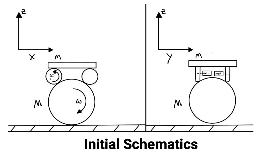
The dynamic model was derived for the planar case and implemented in MATLAB/Simulink, which made it possible to design and study the closed-loop behaviour in simulation before touching the hardware. A PD controller was developed against that model, then transferred to the physical robot and re-tuned against its measured behaviour.
Testing & Validation
Testing ran in both directions: simulation results guided the controller, and the behaviour of the physical robot fed back into the model and the gains.
The open-loop system was confirmed to be unstable, as expected. The controller was then evaluated on the real robot — including its response when released from an initial offset and to disturbances applied by hand. Controller variants were compared on the hardware: adding an integral term produced a slower response and oscillations, so the final controller stayed a tuned PD.
Results & Lessons Learned
The project demonstrated the full path from a modelled and simulated dynamic system to a real robot balancing on a ball.
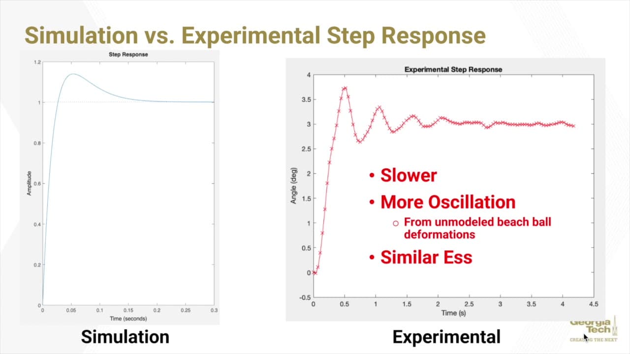
Comparing the simulated and the measured step response showed where the model stops being accurate. The simulation settles within a fraction of a second after a single overshoot; the real robot needs on the order of two seconds, overshoots more strongly and keeps oscillating for several cycles before reaching a comparable steady-state value. The difference was attributed to the deformation of the beach ball, which the rigid-body model does not capture.
The project team received extra credit as the course's “hardest working team.”
What stayed with me is how much of the work sits between the model and the hardware. The structure of the controller came out of the model; the gains that actually worked came out of the physical system — and the largest single error term turned out to be a property of the ball that nobody had modelled.
Technical areas
- Dynamic Modelling
- PD Control
- MATLAB
- Simulink
- Simulation
- Physical Prototyping
- Controller Tuning