Variable-Stiffness Robotic Finger
Antagonistic tendon-driven actuation for dexterous robotic hands
An antagonistic tendon-driven robotic finger with a directly integrated elastic element — mechanical design, 3D-printed prototypes, two instrumented test benches and the control and measurement software used to characterise them.
- Role
- Bachelor's Thesis — mechanical design, prototyping, control software, experimental validation
- Organisation
- Professorship for Healthcare and Rehabilitation Robotics, Technical University of Munich
- Period
- Sep 2025 – Feb 2026
- Grade
- 1.0 (1.0 = best)
- Thesis
- Antagonistic Actuation and Variable Stiffness
Overview
My Bachelor's thesis proposed and experimentally evaluated a tendon-driven antagonistic actuation concept for a robotic finger — intended as a compact, robust and scalable basis for a hand that can later regulate position and stiffness independently.
Two questions were answered experimentally. First: can a silicone element, cast directly into 3D-printed connectors, work as the progressive torsional spring such a concept needs? Second: how does the proposed tendon routing actually behave once two fingers share a single actuator?
The Challenge
Dexterous robotic hands need many degrees of freedom in very little space. At the same time the fingers have to survive physical impact and stay compliant enough to adapt to contacts and to the objects they grasp. Rigid actuators fail the first requirement, purely soft ones the second.
Variable-stiffness actuators solve this by placing an elastic element between actuator and output — but independent control of position and stiffness needs a second actuator, which makes the mechanism larger exactly where there is no room. An antagonistic layout is attractive because it is simple and miniaturisable, and it needs an elastic element with a progressive, nonlinear characteristic.
That is where the concept runs into a hard constraint: no commercial progressive torsional spring exists at finger scale. This thesis therefore investigated whether a cast silicone element can fill that gap, and whether the surrounding actuation architecture holds up on real hardware.
My Contribution
- Designed the mechanical concept and architecture of an antagonistic tendon-driven finger, using rolling-contact joints with extensible elastic ligaments.
- Designed the tendon routing, the whippletree force-distribution mechanism and the mechanical interfaces of the finger.
- Built and iterated the 3D-printed prototypes, including the silicone-to-PLA connector that turned out to be the load-limiting part.
- Designed and built two instrumented test benches: a torsional rig for the elastic element, and a two-finger rig with optical joint-angle tracking.
- Wrote the control and measurement software — PID position-control firmware for up to three DC motors, plus the Python acquisition, marker-tracking and logging pipeline.
- Characterised torque–deflection behaviour, hysteresis and reproducibility of three elastic-element geometries over up to 1000 loading cycles.
- Investigated cross-coupling in the underactuated two-finger setup across five actuation scenarios, 250 cycles each.
- Evaluated everything on real hardware rather than in simulation, and reported the negative result on the elastic element as clearly as the positive one on the architecture.
Engineering & Design
Each finger has three joints — MCP, PIP and DIP — built as rolling-contact joints with extensible ligaments instead of pin joints. The phalanges are not rigidly connected: they roll on each other and are held together by an elastic band running from the metacarpal to the fingertip. That keeps friction low, avoids bearings entirely, and lets the joint absorb impact and compensate ligament stretch during operation.
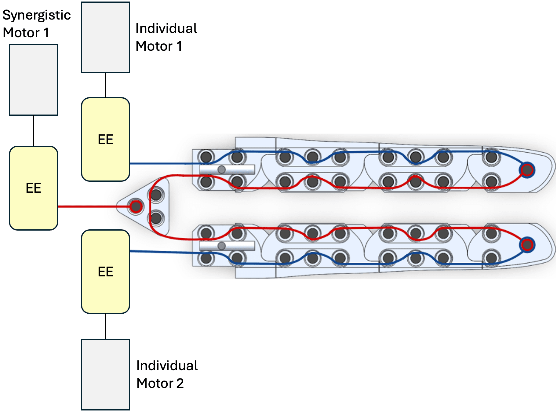
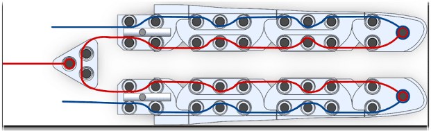
Each finger is driven by an antagonistic pair of braided-polyethylene tendons: a synergistic tendon for flexion, an individual tendon for extension. Both are guided by the same press-fitted steel pins that join the two halves of every phalanx — pulleys with integrated bearings simply do not fit in the available cross-section, which is a compromise that later showed up clearly in the measurements.
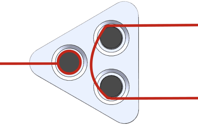
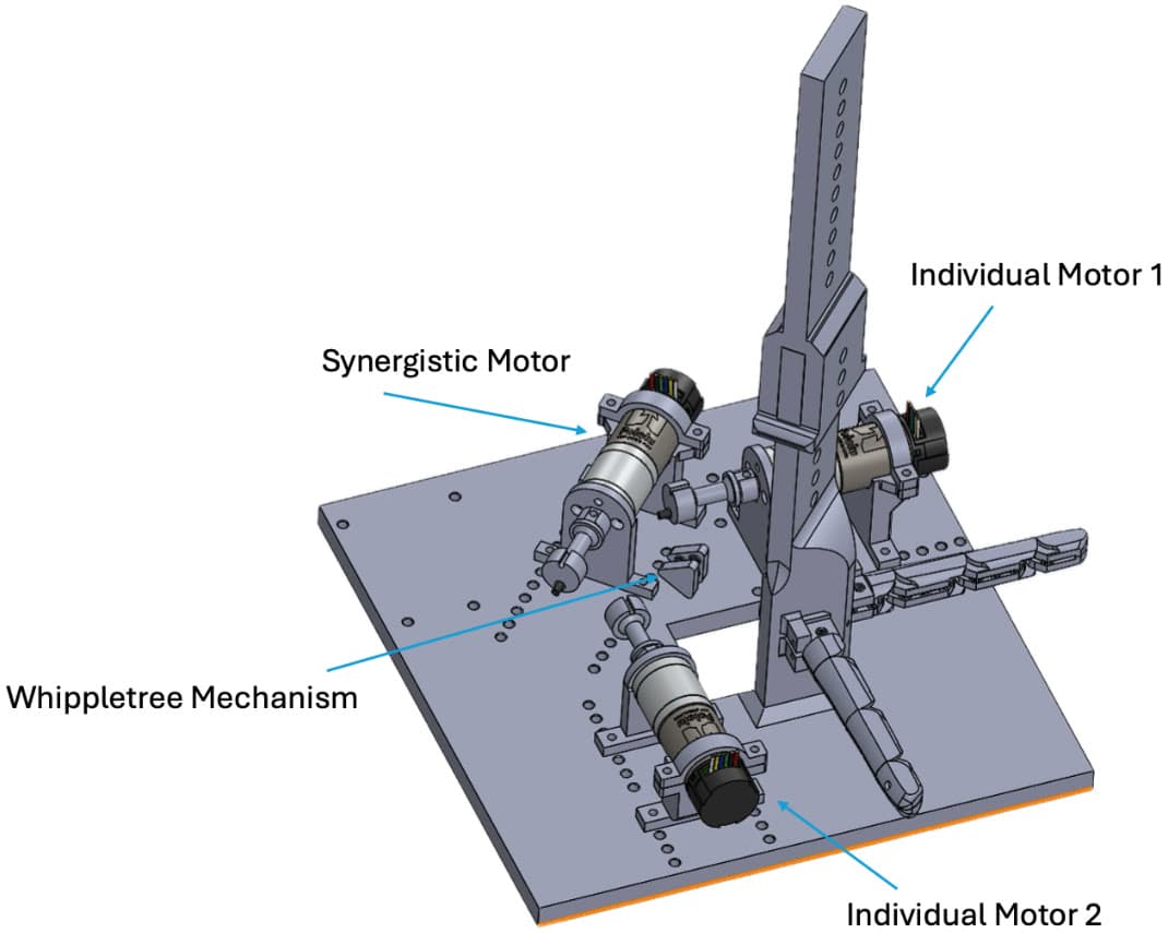
One synergistic motor drives both fingers through a whippletree mechanism, while an individual motor per finger allows selective actuation and constraint. This keeps the number of actuators below the number of joints — deliberately underactuated — and it is the mechanical reason cross-coupling between the fingers had to be investigated.
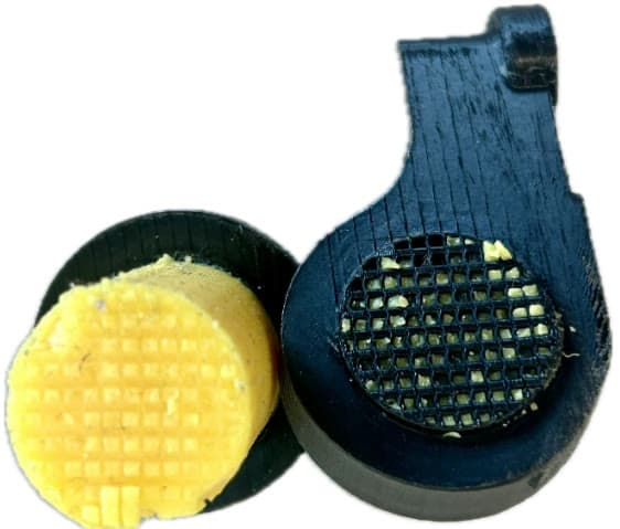
For variable stiffness the elastic element sits between motor and metacarpal and is loaded purely in torsion, so no mechanism is needed to convert rotation into translation. It is cast from a two-component silicone (Shore A 35) directly into a 3D-printed interlocking lattice.
That silicone-to-PLA bond became the limiting factor. The first interlocking geometry delaminated at 0.078 Nm. Redesigning the interface from an abrupt termination into a three-stage gradual transition raised the maximum transmissible torque to 0.436 Nm — a 5.6-fold increase, and the difference between a specimen that survives one cycle and one that survives a thousand.

Testing & Validation
Both experiments needed hardware that did not exist yet, so the test benches were part of the work. Each was designed in CAD, 3D-printed, instrumented, and driven by firmware and acquisition software written for the purpose.
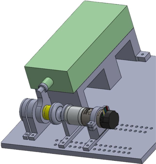
The first bench characterises the elastic element in torsion. A DC motor twists one connector while the opposite connector is held by a force gauge acting on a 31 mm lever arm, so torque follows from the measured force. The gauge is mounted horizontally so gravity does not enter the measurement, and the shaft runs in a locating/non-locating bearing pair to keep axial load out. Loading is quasi-static and incremental under closed-loop position control, with five force samples and a median-based outlier rejection at every angular step.
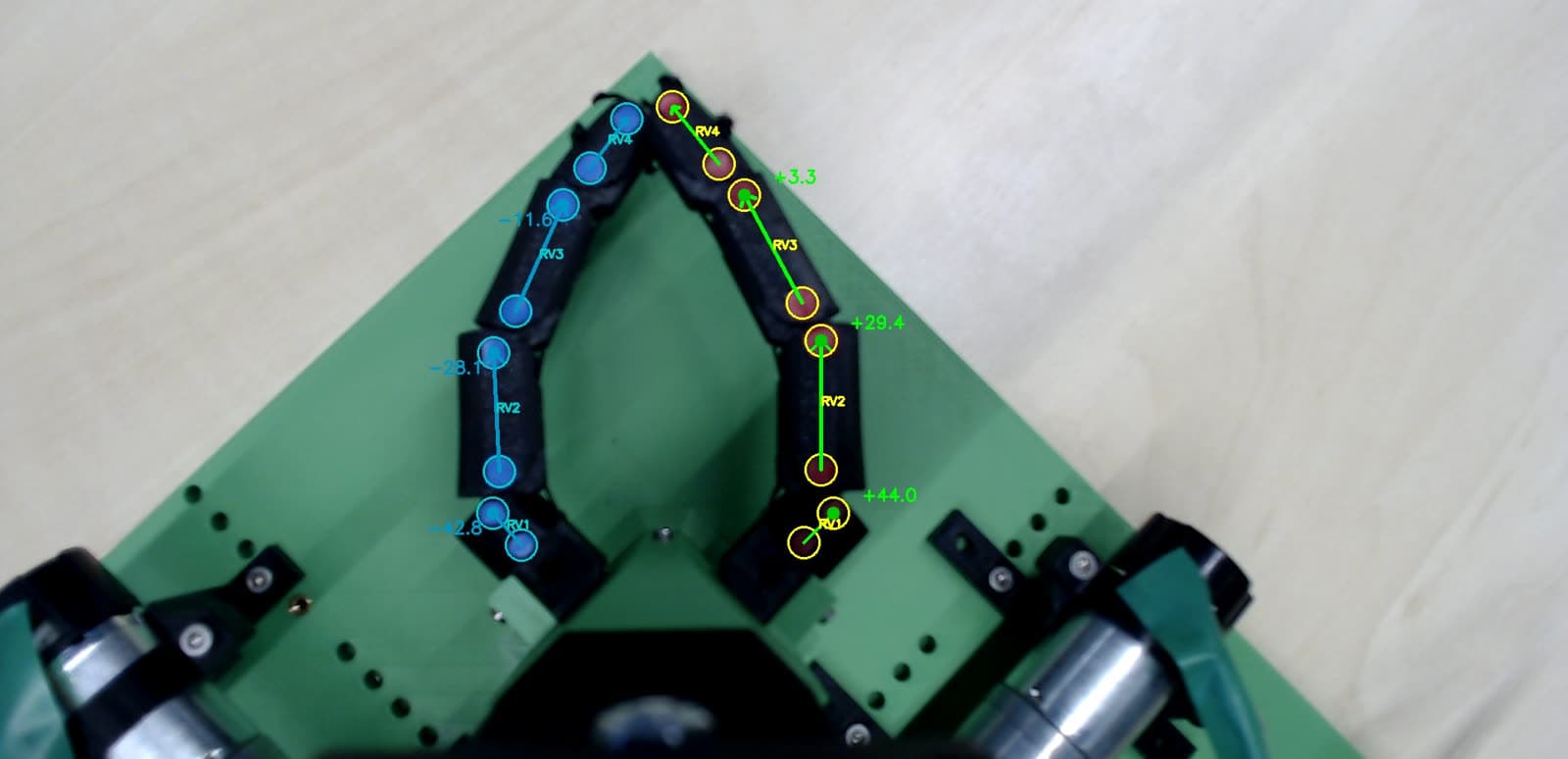
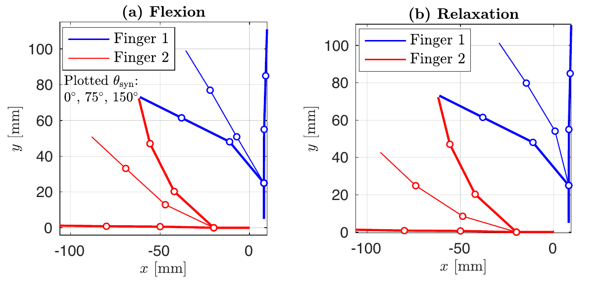
The second bench holds two fingers on a vertical mount together with all three motors and the whippletree, which hangs freely to keep parasitic forces out of the coupling. Joint angles are measured optically: a camera above the setup tracks two colour-coded markers per phalanx, orders them along the finger with a minimum spanning tree, and computes each joint angle between adjacent segment vectors. Because every angle is relative to the neighbouring phalanx rather than a global frame, errors do not accumulate; a calibration routine zeroes out marker-placement offsets before each run. The resulting measurement is repeatable to within ±2° per finger.
Five actuation scenarios were then run for 250 cycles each: synergistic actuation of both fingers, single-finger actuation with the other motor holding position, maximum single-finger flexion, and the two-finger and single-finger cases repeated at the highest tendon pretension the setup allows.
Results & Lessons Learned
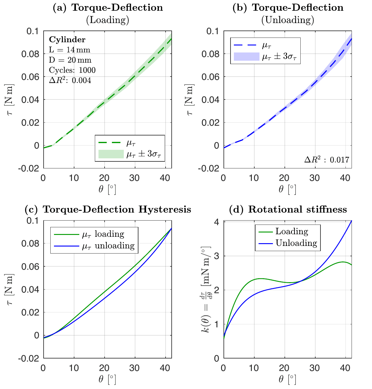
The silicone elements behave well mechanically. All three geometries gave smooth, monotonic torque–deflection curves, good reproducibility over 1000 loading cycles, and limited hysteresis. Shortening the free torsional length raised the transmissible torque for a given motor angle, reaching 0.436 Nm at 117° for the best specimen.
What they do not provide is progressivity. A nonlinearity metric comparing a fifth-order polynomial fit against a linear fit stayed far below the value an ideal quadratic characteristic would give — ΔR² between 0.008 and 0.030 against a reference of 0.064 — and that held even for a truncated-cone specimen with a deliberately non-uniform cross-section. The response is effectively linear, which means roughly constant torsional stiffness, which is precisely what a variable-stiffness actuator cannot use. The conclusion of the thesis is therefore that this silicone is not a suitable progressive torsional spring, and that future work should look for other materials and geometries.
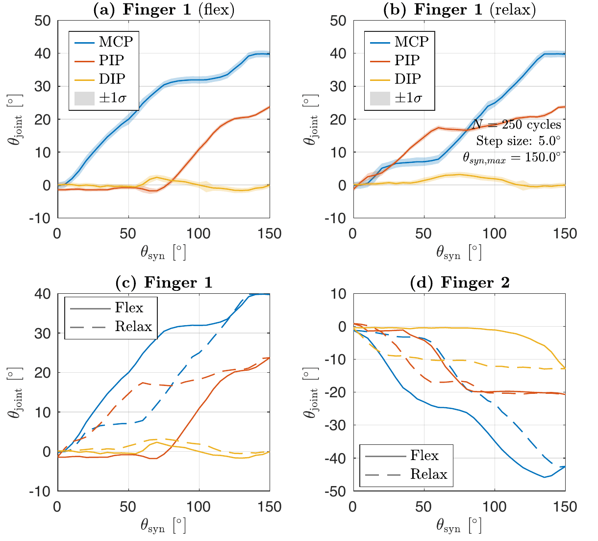
The actuation architecture, on the other hand, worked. Synergistic control of both fingers and selective single-finger actuation are both feasible: a finger can be held in place simply by keeping its individual motor at zero, and the residual coupling stays within the ±2° measurement precision.
At low tendon pretension the joints do not move together. The MCP joint starts flexing as soon as torque is applied, the PIP joint follows once a threshold is exceeded, then the DIP joint — and the same sequence runs in reverse during relaxation. That sequential activation is what produces the pronounced hysteresis in the joint-angle curves. The most plausible cause is friction at the tendon guiding pins: the MCP tendon passes over the fewest pins, and it moves first.
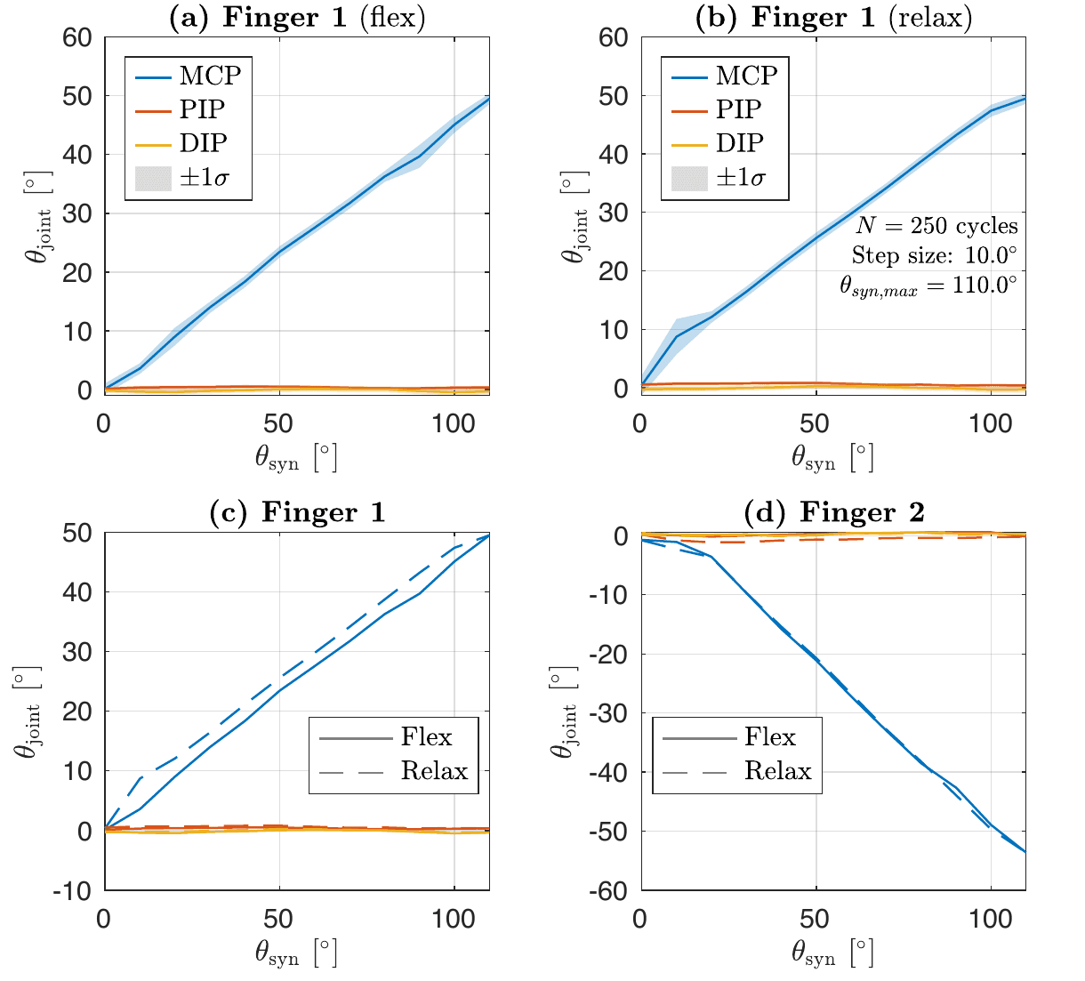
Raising the pretension changed the behaviour qualitatively. Motion then concentrates almost entirely at the MCP joint — up to its mechanical limit of roughly 90° — while PIP and DIP stay near zero and the hysteresis nearly disappears. Since pretension is set by driving the synergistic and individual motors against each other, the same hardware gains an additional degree of actuation beyond position: how motion is distributed across the joints becomes selectable.
Across every 250-cycle run the maximum MCP angle stayed stable, so tendon elongation and slack are negligible. What stayed with me is how much of the outcome sat in things a CAD model does not show — the adhesive bond between silicone and PLA, and the friction of a handful of guiding pins.
Technical areas
- Tendon-Driven Actuation
- Variable Stiffness
- Mechanical Design
- Rolling-Contact Joints
- Prototyping
- Test-Bench Design
- Control Software
- Optical Measurement
- MATLAB
- SolidWorks